Connecting to Raspberry Pi HATs #1006
Replies: 11 comments
-
|
Posted at 2018-10-31 by @gfwilliams Hi, I know what you mean about the lack of interest in shields. I did add http://www.espruino.com/Arduino but I haven't had much feedback on it. However what I've been trying to do there might be a really good place to start? For instance on http://www.espruino.com/arduino-motorshield Basically each bit of hardware has module, and when initialised it expects an object, which has fields I did a similar thing with http://www.espruino.com/Grove as well - albeit just with a 2 element array for that. So for HATs you could define some object with BCM2/3/etc on it which matches how you wired up your Espruino - then each module for a Pi HAT could use that to figure out which pins to use. The really neat thing is you can compile Espruino for a Raspberry Pi, so you could even potentially use the HATs with JS on the Pi (although afaik SPI and I2C aren't supported yet, but you could still use software I2C and SPI) |
Beta Was this translation helpful? Give feedback.
-
|
Posted at 2018-10-31 by veryalien Hi Gordon, Thanks for all the pointers. I'll have a look at the motor board and the Grove modules for more info on how you did it for Arduino shields. |
Beta Was this translation helpful? Give feedback.
-
|
Posted at 2018-10-31 by veryalien Lo and behold, after about 5 minutes of wiring to a breadboard and a black hat hacker... the GFX HAT LCD is working! |
Beta Was this translation helpful? Give feedback.
-
|
Posted at 2018-11-01 by @gfwilliams Wow, nice!
This sounds like everything's good. I think you want to find the resistor divider setting where 0.5 for contrast is the most readable, and then tweak it more gradually by adjusting the contrast. There is a Bias setting as well - you could try manually doing: And see if that helps - the actual setting I use on Pixl (which uses the same display) are here: Whereas the defaults for the ST7565 module are http://www.espruino.com/modules/ST7565.js LEDsTurns out I'm actually using that LED driver on a board I'm doing for someone else. The code isn't public yet so I'll share it here and hopefully you can get some stuff done with it: |
Beta Was this translation helpful? Give feedback.
-
|
Posted at 2018-11-01 by @allObjects ..no desire to buy Arduino shields - with the messed up header spacing - when no need... may be pixl changes this a bit... but I'm not sure. And the other way round either: Arduino community interested in Pixl to use as ready made display that could be controlled with simple serial.... To even think of that, Pixl would have to be able to path the pins to the headers... or have a second row of headers with some patching options.. w/ jumpers, for example... But I guess that was never the idea... and space is not there either. With a second row of headers, some wire soldering on the board could do... or a patching shield with two rows of headers... but that's a lot of hardware... Getting an Arduino user try Espruino Pixl in order to have some more use - and ROI - on the hanging around shields... that may have been a goal... was it? |
Beta Was this translation helpful? Give feedback.
-
|
Posted at 2018-11-04 by veryalien Hi Gordon, I've got it working... mainly after I realised I needed to connect 5V from the Pico to the GFX HAT to actually get the LEDs to light, doh! This line seems to be from your project, it's not needed, I removed it, I'm not sure what it's supposed to do: LED_PWR.set(); // LED on So now I have the bling-bling RGB backlight on the GFX HAT working with Espruino. 18 LEDs in total, 6 RGB all individually controllable. What a coincidence that Pimoroni used 6 RGB LEDs for the HAT backlight with a SN3218 controller! ;) Now to attack the CAP1166 with Espruino for the touch pads and the white LEDs indicators. |
Beta Was this translation helpful? Give feedback.
-
|
Posted at 2018-11-04 by @gfwilliams
Ahh, the LED controller has an enable line - it may just be tied high in the HAT as there weren't worried about power usage too much? |
Beta Was this translation helpful? Give feedback.
-
|
Posted at 2018-11-04 by veryalien Oh I see, you mean the hardware shutdown mode SDB on pin 24? It appears that you can use the software shutdown to make the LEDs flash, without manually setting them all off and then back to their current values or by enabling/disabling the LED outputs individually. The states of all the registers are kept during a 'shutdown', only the outputs are turned off. Just toggle register 0, bit 0, off and on regularly to make everything flash. That could simplify some code. The interesting things you (unfortunately) find buried in datasheets! |
Beta Was this translation helpful? Give feedback.
-
|
Posted at 2018-11-04 by veryalien So that's the GFX HAT done and dusted! Well, it's working on the bench, let's put it that way. It needs cleaning up and repackaging a bit. Couple of points: After I ordered a Pixl.js (from Pimoroni UK, still waiting), I noticed that the chip pins are 3.3V only, 5V is going to kill them, but that is the same as the Raspberry Pi. Then I noticed that the Arduino is fundamentally 5V, but there are '3.3V only' shields. I'm messing around with a Pico and raspberry HATs most of which have both 5V and 3.3V pins connected when on a Pi. The Pico has 5V tolerant pins. I'm wondering how many Arduino shields and raspberry pi HATs can be fully used with only 3.3V? I've had problems with other boards and level shifters in the past trying to make the sure that the supply voltage and the GPIO pins are correctly shifted at both ends. I'm considering buying one of these boards to attach to the Pixl.js, to make adding HATs and pHATs neater without using a black hat hacker board. But I've already noticed that it doesn't have level shifting on all pins, just selected ones. https://www.abelectronics.co.uk/p/66/arduino-uno-to-raspberry-pi-adapter I'm no electrical expert, but I'm running the GFX HAT using only 3.3V with the Pico. This means I've connected both the 5V and 3.3V pins on the HAT to 3.3V from the Pico and it's all working as expected. Please shout at mean if I've missed something somewhere in the above! As a side-effect of not sitting directly over the Pi 3+ processor and using the lower voltage, the GFX HAT is not getting hot or even warm. When it's on the Pi and all the LEDs are on at full whack, it gets extremely hot, which seems to affect the LCD contrast after a couple of hours. I don't like this as I think it might be a design flaw, but I hope not. |
Beta Was this translation helpful? Give feedback.
-
|
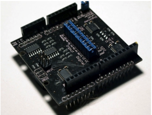
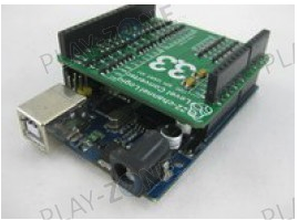
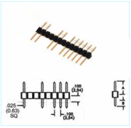
Posted at 2018-11-05 by @allObjects With STM32F#... pins being 5V tolerant for incoming signals and being able to drive outputs up to almost 3.3v, any 5V shield can do, and the 5V shield can even feed the Espruino side when done correctly. Push comes to shove, a level shifter board has to be plugged in between... may be such do already exists, last but not least because some peripherals are anyway 3.3V only and not all have level shifters on them and are without such anyway cheaper... digiStump has a cost effective solution... the description though is not so convincing... http://digistump.com/products/51.. And I like the Swiss-Army-Knife-like solution... just a bit expensive... https://www.play-zone.ch/de/level-shifter-shield-5v-3-3v.html from play-zone, in Steinhausen / Kt Zug, Switzerland... - looks pretty clean - sorry for the bias... ;-) For both, you place plain male-pin-header strips between female pixl and female 3.3V shield headers with hits and misses - teeth and tooth gaps - to just get the connections hour interested in... (you have to move the plastic strip to the middle of the pins). Attachments: |
Beta Was this translation helpful? Give feedback.
-
|
Posted at 2018-11-06 by @gfwilliams Just to add, while many (not all) of the STM32 pins are 5v tolerant, the Pixl.js and the other nRF52-based boards are definitely not 5v tolerant on any GPIO pins (although the Pixl/MDBT42 breakout have voltage regulators so can be powered off higher voltage). As I understand it the official Arduino Due board isn't 5v tolerant either, so if any shield says it is Due compatible then you're fine. The vast majority of the Arduino shields I've seen are ok - they seem more concerned with not blowing up the 3.3v circuitry on the shield with Arduino's 5v than they are about going the other way - since if they output 3.3v logic signals, that's fine to input to an Arduino's 5v. However if the logic on the shield itself is meant to run at 5v then you could have an issue, unless you can run all the logic on that shield at 3.3v instead of 5. If in doubt ask though and I can try and take a look. It'd be great to build up a list of Arduino shields that do work fine. |
Beta Was this translation helpful? Give feedback.
-
Posted at 2018-10-31 by veryalien
I'm interested in driving raspberry pi HATs , pHATs, and other accessories with Espruino.
The pixl.js has Arduino shield compatible headers (my pixl.js has just been ordered), but I was thinking I could do something similar with my Pico and my large collection of raspberry pi HATs.
pinout.xyz has lots of useful HAT pin and driver info and the hacker breakout boards should make it easy to connect everything properly.
Has anyone done something with directly connecting espruino and HATs? It's probably not exactly rocket science. The trick is obviously just getting all the right pins in all the right places at both ends and setting up module code correctly (and making sure not to put 5V and 3V3 in the wrong places!). I was thinking that I could reuse shared espruino code from other people if they've already connected successfully to particular HATs.
Many of the HATs have pretty standard sensors or chips to drive the relevant HAT hardware, some of these devices have already got espruino modules, so I'm surprised that I can't find anything about interfacing to them when they are built into HATs. Lots of them are just I2C devices which shouldn't be that complicated to get working. Of course the de facto way of interfacing on the Pi is to use python, so some conversion to espruino will be needed.
I've been looking around the Espruino forum and I can't find anyone else trying to do this. I might be looking in the wrong places?!
EDIT: I've now found some, but really not that much, info regarding using espruino with Arduino shields, so perhaps people are just working at the module level and the wiring is an exercise for the student?
Has anyone already done something similar with raspberry HATs? If so, please let me know.
Beta Was this translation helpful? Give feedback.
All reactions