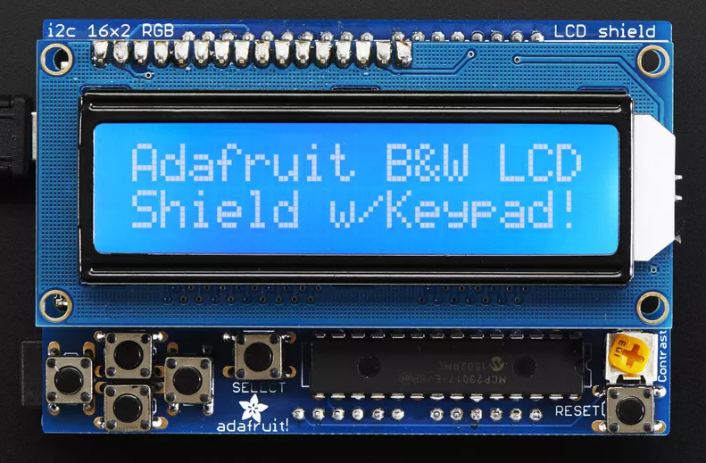
16x2 LCD shield w/ Keypad #780
Replies: 9 comments
-
|
Posted at 2015-08-01 by DrAzzy Screen is one of these http://www.espruino.com/HD44780 It's driven in 4 bit mode, it looks like. Then everything is driven by the mcp23017 i2c pet expander. Nobody has written a module (what Arduino would call a library) for it that yet, probably since the espruino boards aren't pin starved quite like an Arduino is. |
Beta Was this translation helpful? Give feedback.
-
|
Posted at 2015-08-01 by @allObjects First, you have to talke to MPC23017 I2C expander and configure it that through it you will talk to the HD44780 LCD controller. Latter you will then have to configure as well before can actually send commands and data to show something on the display. There are many roads to get there and you can use all information available to you, such as the data sheets fort the MPC23027 expander, the datasheet/schema of the 'shield', the HD44780 LCD controller, and - last but not least - the driver software/library module form the 'shield provider'. The driver softwrae/library module is written for Arduino and its programming language. If you are used to read that kind of code and are familiar with the related modules used and the hardware, it for sure helps... and if not that much, at least the comments in this code can be In separate posts I will go a bit through the
After working through these steps, you may then want to create an Espruino module that you can pull into your application code with a single line, looking like the second in this code: Please be forgiving to me when I do not get it right on the first cut... I don't have the 'shield' at hand. I run this all as a thought experiment... I can not verify, but you - @scottking - can do so. I appreciate your help. Please use the forum's message feature to provide me with feedback and I will adjust my posts.Attachments: |
Beta Was this translation helpful? Give feedback.
-
|
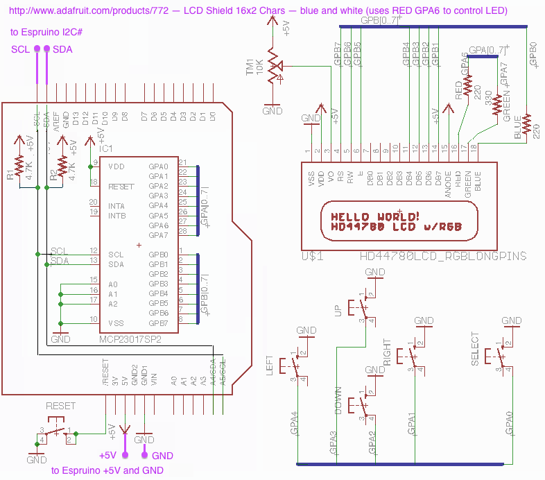
Posted at 2015-08-01 by @allObjects Discussion of the hardware of the LCD Shield Kit w/ 16x2 Character Display / Blue and White (adafruit.com/products/772)... First of all, why comes the MPC23017 I2C expander into play? For a similar reason as the HD44780 is there: to reduce the number wires to control the device (and to offload the driving device / mC) - bottom line to simplify the use. I while back I used the 8-bit Ubicon SX mC - RIP ;-) (originally SceniX, and now Qualcomm) - to drive the HD44780 and backlight LED directly as available from a similar product to Standard LCD 16x2 + extras - white on blue (adafruit.com/products/181). The module occupied a lot of I/O pins from the uC, even in the 4 bit (parallel) mode: at least 6 pins/wires - plus one more for the back light LED, if you want to control it(s brightness) through code. The savings of 4 lines vs the 8 bit parallel mode (total 10 respective 11 pins/wires) is paid with more complex code and slower update time (speed is relative, though). Using the MPC23017 I2C expander, one needs only two (2) pins/wires: one for serial clock (SCL) and one for serial data (SDA) - not counting the wires for ground (GND) and power (+5V). *Make sure that you always connect Espruino's and the 'shields''s GND, even when you suppply the 'shield' with a seperate power supply and not with Espruino's 5V. * Note, that multiple I2C devices can 'sit on the same I2C channel' of the mC, therefore, each of the I2C devices has an address defined by jumpers. The MPC23017 has 3 address lines - A0..A2 - which allow 8 of these to be on on single I2C channel. Btw, the MC23017 has a sibling MPC23S17 , which supports SPI connectivity with even faster serial communicaiton, but requires an additional line per chip to select the chip that is to communicate. If though something should talk back to the mC by interrupt, such as the event of a button press or release, one or two more wires/pins are required to connect to one or both interupt pins of the extender. The buttons can always be polled - asked whether theay are pressed or released - but polling is not a preferred approach, since it uses mC computing cycles and makes programming (more) complicated (Arduino 'people' claim the opposite, and they are right... depending the circumstances and the Arduino primarily supported 'loop model'). Espruino goes - and has to go - for the event / interrupt driven approach, which allows easily to add things due to the absence of the loop. Enough of the (philosphic) discussion. Let's look at the 'shield' hardware schematic to understand how we have to setup, configure, and talk to the MPC23017 I2C expander. See attachments ('photoshoped' from the 'only' available adafruit/Adafruit-RGB-LCD-shield/blob/master/adafruit_rgblcdshield.sch - LCD Shield 16x2 Chars schematic. We already know that we have to talk I2C to the expander. And we can see that we have to use address 0 - because A0..A3 are connected to GND. But what we have to talk can be seen how the GPX# - General io Pin of ports A and B (GPA0..7 and GPB0..7) are connected to the HD44780 LCD controler and the rest on the board, such as the back light LED and buttons. As @drazzy pointed out, the LCD controler operates in 4 bit (nibble) mode: only 4 of the 8 data lines that go to the LCD module (with the LCD controller and the actual LCD are connected): GPB1..GPB4 to D07..D04. Here the complete mapping: | GPA0 <---- Select button 0 | GPB0 ----> Blue LED Attachments: |
Beta Was this translation helpful? Give feedback.
-
|
Posted at 2015-08-02 by @allObjects *** DRAFT ...in progress *** Configuring the MCP23017 I2C Expander The nice part about the Expander is that it initializes as all inputs. Therefore, reading the buttons should work right of the bat. Connect with Espruino standard as follows (disconnect Espruino first from power/USB, and reconnect after making the connections): | Espruino --------- 'shield' Copy this code into the edit pane of Espruino' Web IDE and upload it. The expander has a nice feature: the input can be reversed so only masking is required. Activating this feature is part of the initialization. At the same time we will configure some of the pins as output in order to drive first the back light LED and later the LCD module. |
Beta Was this translation helpful? Give feedback.
-
|
Posted at 2015-08-02 by DrAzzy Are you working on a module for this? I had a thought.... Wouldn't it be cool if when you called MCP23017.connect() it would return an object with 16 members, each with set(), unset() etc methods, ie like this: http://www.espruino.com/Reference#Pin ie: {"A0":{"set":function.....},"A1"...} Then, you could use them just like any other pin... so: Right now though, the pin class doesn't have enough functionality to do that for all cases (though it's fine for this case). But even with the current pin class (lacking pin.mode() ), this could be made really painless to use with this LCD display and a lot of other modules. The modifications to the HD44780 module should be almost trivial. Writing the MCP23017 module to return things that act like pins, not so trivial - but imo it's clearly the Right Way to do a module for a port expander. |
Beta Was this translation helpful? Give feedback.
-
|
Posted at 2015-08-02 by @allObjects @drazzy, you make a good point... for just controlling output it works quite well. When it is in conjunction with any other things behind - especially with buttons that should trigger events - the MCP23017 is so versatitile, that I would see two modules... at least for the start. Of course, implementing the latter would benefit from the implementation of a plain MCP23017 extender. Before I confidently understand the dynamic aspects that are need - such as when to then send something to the extender after having done all the 'set' operations - I could think of this. Maybe I see it too complicated and it is just very simple. Since we are living in an resource constraint world - speed and memory - I see less generalization and more specialization/dedication to take place. That does not mean 'no generalization, just specialization', but it means to pick the appropriate degree of generalization. What I miss on this shield is that the intA and intB connections are not on pins... no wonder it is an Arduino shield with the Arduino loop programming model - with polling... a totally different software architecture than Espruino - with eventing, and I love the latter... |
Beta Was this translation helpful? Give feedback.
-
|
Posted at 2015-08-03 by @gfwilliams Sorry I'm a bit late with this... Actually being able to create your own pins would be very cool. Even better if the existing Arduino-style functions could interface to them as well, but I wonder if trying to get them working could end up being a bit of a hack. Also, although it's not an issue with this LCD, speed would be pretty poor as it'd be doing an I2C write for each pin state change. In this case though, the HD44780 module already provides enough abstraction to do this nicely, as you can just provide your own |
Beta Was this translation helpful? Give feedback.
-
|
Posted at 2015-08-03 by DrAzzy Oh crap, there's the digitalWriting to a bank of four of them at once. Which can be done with port expander, but not compatible with my soft-pin idea... The HD44780 provides a straight-forward way to extend (and does almost all the work - I'd think it would be 5-10 minutes of work tops to get that side sorted out once we had a driver for the port expander. mmm... I'm going to start a new thread to focus on the port expander, since this is a matter we need to think carefully about; it requires some thought to make it maximally useful... |
Beta Was this translation helpful? Give feedback.
-
|
Posted at 2015-08-03 by @allObjects Instead of seeing the MCP23017 and bit-peek and -poke things together, I was more thinking along the lines of a modified HD44780 module - called HD44780MCP23017 - which has exactly the same API as HD44780 (in 4 bit mode) but hides that there is an MCP23017 inbetween... I feel that is a bit what @gordon is talking about. The connect may be a bit different, because instead of passing pins for the control and data lines, an address and I2C lines have to be provided. To have extra port expander module(s) in place as @drazzy suggests, is a good point. I hinted plural, because there are multiple expanders out there: 2x8bit or 16bit - as the MCP23017/MCP23S17 types (for I2C and SPI), and 8 bits. |
Beta Was this translation helpful? Give feedback.
Uh oh!
There was an error while loading. Please reload this page.
-
Posted at 2015-08-01 by scottKing
Firstly, here is a link to the exact model I am trying to use
http://www.adafruit.com/products/772
I am trying to wire this up, I've checked the module reference and tried a few of the various LCD drivers, but I'm stumped. Does anyone know how to connect this model? I'm pretty new to microcontrollers and this is beyond me.
Praise to any and all help!
Beta Was this translation helpful? Give feedback.
All reactions