Add ATmega324PB #8
Conversation
|
Added also ATmega328PB and its memory variations (48/88/168) |
There was a problem hiding this comment.
Thanks for the PR!
My comments:
- Maybe better rename the symbols/components to e.g. "ATmega48/88/168/328PB", or at least mention it in the description to which models the symbols/components apply?
- Remove the underscore from symbol names (i.e. "ATmegaxx8PB_functional" -> "ATmegaxx8PB Functional").
- Remove the "Reset = PC6" label from symbols. Rename the component signal to "PC6/nRESET" instead.
- Move the "{{NAME}}" and "{{VALUE}}" labels out of the symbol body, e.g. name to the top left and value to the bottom left (or right, if it looks better).
- The component "ATmegaxx4PB" has no default value set.
- In the "ATmegaxx8PB_functional" symbol, pins are the other way around as in "ATmegaxx4PB_functional" -> change pin order (Px0 at top, Px7 at bottom).
- GND1 and GND2 should be combined into one component signal "GND", and only one GND pin added to the functional symbols.
- Actually I think the "physical" symbols could be made generic and added to the LibrePCB_ICs library (like the "Generic IC" symbols there). Then the symbols could be used by other 32/44-pin components too. And the term "functional" resp. "physical" is no longer needed in the symbol names. Or what do you think @dbrgn?
cmpcat/a1a5cd04-cfcc-47da-841c-d0cf666fe417/component_category.lp
Outdated
Show resolved
Hide resolved
I was waiting for that observation !
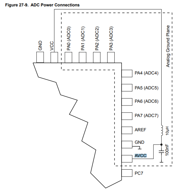
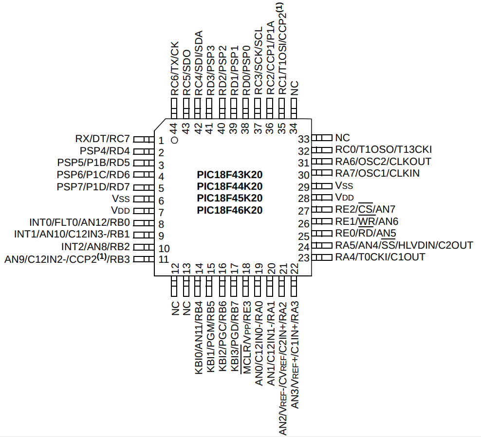
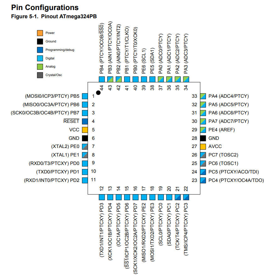
The physical symbol can't be generic as power pins and port are not always in the same place in different micro-controllers Here is a Microchip PIC TQFP44 And here ATmega324PB |
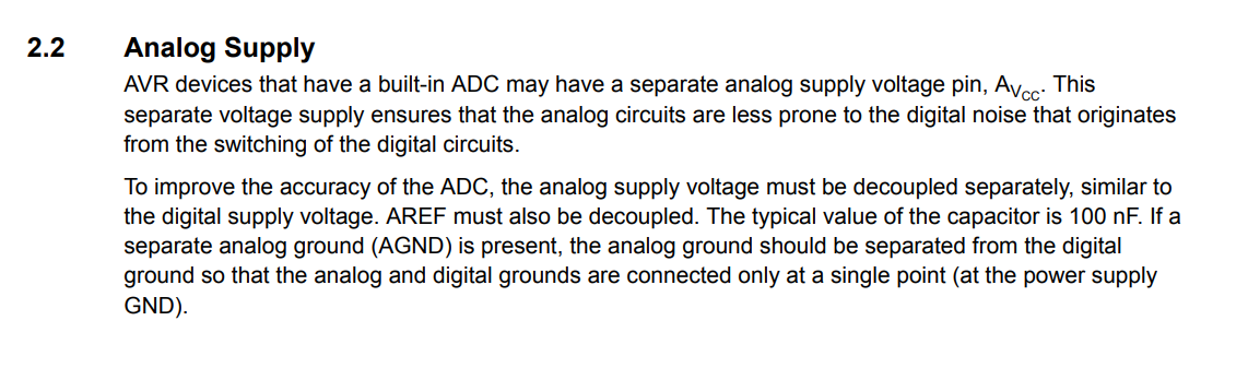
So how should we handle this case? It is quite common to have a different Analog GND (AGND) and the GND for the rest. |
Co-Authored-By: U. Bruhin <[email protected]>
Hmm that's a tricky thing. Since the two GND pins are (probably) electrically identical (otherwise Atmel would name them differently), I'm not sure if it makes sense to handle them as separate signals in the component. With the names GND1 and GND2 you still don't know (in schematics) which one is which. If you want to draw a separate GND plane around all the analog pins, shouldn't this be a topic related only to the board editor?
That's why our generic IC symbol have their pins names just "1", "2", "3" etc, so they can be used for whatever signal you like. For example pin "5" is used as "GND" in one component, and as "VCC" in another component, that doesn't matter. |
Usually one wants at least different net names to be able to easily highlight the different GNDs. Also sometimes GND and AGND are connected via some kind of decoupling (L, C or whatever), or just a 0-Ohm resistor / bridge to have a "star" distribution of the GND signal. See https://www.analog.com/en/analog-dialogue/raqs/raq-issue-159.html for example. |
|
@rnestler I am not sure the link you provide can represent the situation. |
It is relevant if you want to separate the GND for the analog parts from the GND of other parts of the circuit which may draw more power. But you are right that it doesn't represent the issue perfectly. Maybe https://www.analog.com/en/analog-dialogue/articles/staying-well-grounded.html# is a better resource. |
|
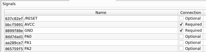
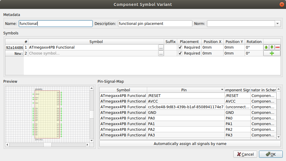
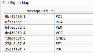
I have made all changes except the GND prob. First we are OK that if I put only one GND pin in functional symbol, I should make the same to Physical symbols in order to use them in the same component ? And when I rename GND1 to GND and suppress GND2, I encounter some problems : I get an orphelin pin-signal-mapping How can I delete this without breaking everything ? And also in pad-signal-mapping of devices, I still get old name : |
There is still an unresolved issue: #8 (comment) 😉 And the symbols still have an underscore in their name (see #8 (review)).
Hmm I'm not sure if I understand correctly. The physical symbol should still have all pins since it represents the package. And if you make the symbol generic (pins named "1", "2", ...) as I suggested in #8 (review), there is no conflict between the two GND pins. FYI, to simplify things and thus getting this merged sooner, you could even remove the physical symbol variant for now and add it in a separate PR later ;) |
|
Should I update version from 0.2.1 to 0.2.2 ? And for the name, I think that AVR are more Atmel than Microchip. |
|
Seems there also a problem because I have used the nightly build to make changes. How should I solve that ? |
…-fr/Microchip.lplib into add-ATmega324PB-ATmega328PB
So I have added ATmega324PB in TQFP package.
I have not added the VQFN version as I haven't found the footprint.
I made both functional symbol (default one) and physical symbol (using physical pin placement).
I have also created a new category called "AVR 8bits Microcontrollers" and put this one and also ATtiny85 inside.
Finally, I have fixed a little mistake in the ATtiny85 description (8 kbytes instead of 8 bytes of flash).
Please tell me if this is ok for you and I will add ATmegaxx8PB (48/88/168/328).
Thanks.