Pedestrian Detection, Obstacle Detection, GPS and Google Map API based navigation
Our product uses a combination of wire and wireless communication. Pedestrian detection function uses GPIO connection between the Raspberry Pi 4 and STM32F4 for the purpose of simplicity. In our former testing cases, we encountered issues of the GPS signal lost under snowy weather conditions. Then we replaced it with a better GPS module BerryGPS to ensure the stability of the signal connection under any circumstances. For the control system, we use GPIO pin communication as well. Because we have most of the signal processed in Raspberry Pi 4 so that moving instructions could be conveyed by sending different pin values to the STM32F4.
-
Functional Requirements: Moving Functionality, Pedestrian Detection Functionality, Navigation Functionality, Center of Road Detection Functionality, Obstacle Detection Functionality.
-
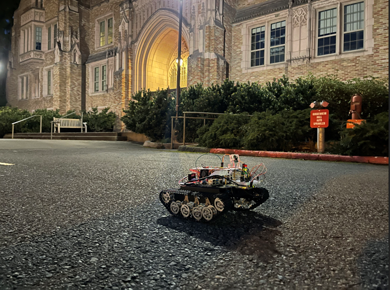
Size, Weight, and Cost Requirements: Height: 9.5cm, Width: 19cm, Length: 27.5cm, Weight: 3.5kg, Cost: $400.
-
Power Requirements: 2 9V batteries in series providing 18V of voltage
-
Communication and Interface Requirements: GPIO connection between Raspberry Pi 4 and STM32F4Discovery
-
Control Requirements: L298n control module
-
Computation Requirements: Raspberry Pi 4, STM32F4Discovery
-
Software and Firmware Requirements: Python 2.7 or above, STM32 with firmware version of V2.J27.M15, OpenCV 4.0
-
Precision and Accuracy Requirements: BerryGPS compass
-
Test and Validation Requirements: Flat ground, away from strong magnetic field
-
Safety Requirements: Away from crowds
-
Environmental Requirements: City roads
For this task, the goal is to implement a pedestrian detection function on our robot, so that the robot can detect if there are people ahead and stop its movement to avoid collision with the person.
The steps to implement this function:
- Implement the pedestrian detection function
- Implement the distance estimation function
- Connect the Stm and pi to use calculated result to control the car
This can be achieved by the inner library of OpenCV[2]. The HOG human detection function[3] implemented in OpenCV can help us to process images and return the value of each person's position by xy coordinates. For example if the people detected by the HOG function are at pixel (80,100) and have a width of 20 and height of 40, then these results would be returned by the hog.detectMultiScale() function.
As the whole convolution network is given, we do not need to manually train the heights. And we can automatically obtain the number of people in the range of the camera and the relative position of the pedestrian. This needs experimental data to decide at what distance the robot needs to stop.
Then finally connect the GPIO of STM32F4 and Raspberry Pi. As main calculations are done on Raspberry Pi, we need to send the signal to STM32 board and make the car receive the signal to light up the warning LED when the camera detects a human approaching and stops the robot car.
Pedestrian detection monitors the road conditions ahead of the robot car’s moving direction and we decided to carry a real-time processing of the image data captured by the Picamera on the robot car. However, due to the limit of hardware’s computing power, our pedestrian detection system has a delay of less than 2 seconds. As a result, we pushed away about 2 meters of the warning line from our robot car so that the control system would have enough time to react. Nowadays, people are concerned about privacy protection due to transparency of all kinds of information on the internet. The camera based pedestrian recognition might be accused of violence of privacy. It seems the pedestrian detection is not necessary since lidar can also be used to avoid pedestrians by treating them as obstacles. An improvement could be made by lowering the camera close to ground level which avoids shooting the human face.
Our teammate Jasmine implemented a great road detection to control the position relative to the road. For this task, the goal is to implement a road recognition function on our robot, so that the robot can monitor if it is moving on the right track rather than step on the grass or somewhere dangerous. The “raw” pictures we took from the picame are hard to detect as there are too many details in the image. As a result, we need to resize the image properly and denoise it prior to making any process on the image. Afterwards we take a certain pixel as the “reference pixel”, and consider it as the road we are on. Then we let the computer iterate through the whole image to identify the road and unrelated obstacles.
The steps to implement this function:
- shrink the image using interpolation method to decrease the runtime
- take the “reference point”
- extract all pixel values that are close to the “reference point”
- analyze the road shape
- compare left and right side of the road to see if the car is not in the center of the road
This is a newly-designed detection algorithm only for raspberry-pi systems. It can Successfully detects the center of the road and the position of the road. Raspberry Pi 4 has limited computational ability, and it would be taking too long to accomplish a perfect road detection system using convolutional neural networks. It takes a few seconds to react which is too long to warn the robot under emergency situations. A simple solution would be replacing it with a powerful CPU instead. We have also implemented several manipulations of the image before sending it into the detection system, so the image is shrinked to a certain status where the image is not too obscure but detailed enough for processing. To make the center of road detection have a smaller runtime, we did lots of manipulation to the algorithm so that the function can be computed in a relatively short time. However, as we still need to process the image and iterate through each pixel in the image, and we do not want to shrink the image too much to lose its details, there is still a delay of about one second when integrating the algorithm with the entire system. Even though we cannot completely eliminate the delay, we had spent time on shortening the delay. As a result of the limitation of hardware’s computing power and the complexity of road conditions, we decided to abandon the road recognition system on our product prototype. In our testing cases, when the robot car passed through a rampway, the center of the road detection program started causing malfunctions. Because the angle of the camera is unable to adjust, the road portion of the image data captured by the camera decreases significantly which causes the center of the road detection program to fail to calculate the reference vector direction of the image. In addition, the center of the road detection function occupies a lot of computing units, so we found it difficult to implement a real-time processing of this program. As a result, we decided to abandon this functionality.
The main goal of this task is to implement a self-navigation system on the delivery robot car. In order to navigate to our destination, we utilized Google Direction API and a GPS module. Our robot will prompt for destination and send a request to Google Direction API asking for the fastest route from the current location to the destination. Google Direction API divides the route into steps and each step has a starting location, an end location, and a maneuver. By comparing the coordinates of our robot and the end of step coordinates, our robot can tell if it arrives at the end of the step. Once it arrives, our robot will follow the maneuver instruction by turning left or right and then start the next step until it arrives at the destination.
The steps to implement this function:
- Fetch GPS data.
- Parse GPS data into coordinates.
- Send a request to Google Direction API.
- Parse the response into steps.
- Set up a variable step_num for step numbers.
- Compare current coordinates with end of step coordinates.
- If the distance between the two coordinates is within the threshold, do the maneuver or arrive at the destination; otherwise, keep going.
During the development of our navigation system, there had been a few issues with our GPS module. First, when the weather was really cloudy our GPS module would not be able to detect any satellites and receive data. This also sometimes happened when it was in an indoor environment. The solution to this will be to replace it with a better GPS module and try to schedule test days with good weather. Another issue was the precision of the GPS data from both the GPS module and the Google Direction API. When we had them work together, we relied on the coordinates from the GPS module and Google Direction API to determine whether our robot arrived at a certain location. Sometimes the bad precision led to missing a turning point, turning too early or too late. In order to solve this, we used a threshold value to allow a certain amount of errors when comparing the coordinates and we set the threshold to a value which works best in the real world condition after lots of testing.
The self-driving robot needs to avoid crushing obstacles such as bench, stone on the way of delivery. This obstacle dodge function would help the car to avoid crushing on the way. The concept of the 2D lidar is similar to the sonar sensor. It sends out the impulse of laser light and receives the reflection bounced back from the object. Unlike the sonar sensor, it has a rotation base such that it can scan the surroundings around the robot. Through the RpLidar library[1], we are able to extract the information in an array data structure. The values it returned are the absolute degrees (from 0 to 360 degrees about 180 sample points) regarding the front of the robot, the intensity of the laser impulse (aka signal quality) and the distance from the object in millimeters. We programmed the lidar to send a yield signal to the robot whenever an object appeared within +60 and -60 degrees about 30 cm from the front of the robot. It also checks 3 meters from the front of the robot which double checks whether the pedestrian exists or not for the pedestrian detection system.
Pedestrian detection test was performed successfully from late January to early February. During the testing we found that due to the limit of hardware’s computing power, our pedestrian detection system has a delay of less than 2 seconds under real-time processing. As a result, we pushed away 2 meters of the warning line to about 6 meters from our robot car so that the control system would have enough time to react. Now the program is able to detect an approaching pedestrian about 6 meters away and trigger a warning signal to the robot car which will light up the STM32’s blue LED and stop the robot car until the warning signal is removed.
In our first road test, we are able to control the motors via the L298N module by providing the turning, forward and stop commands. However, we notice that with default equal voltage output, the motor on each side generates a different rotation speed. The right motor generates more power than the left which gives us a slight left turn when we try to go straight. Secondly, we test the navigation system which is based on GPS signal and Google Direction API. However, due to the cloudy weather and the non-sensitive GPS sensor, we are not able to get the satellite to locate our robot and receive the navigation information. Finally, we test whether the robot would yield for incoming pedestrians or crossing pedestrians. The pedestrian detection performed as we expected. Whenever a or multiple pedestrians are detected, the robot will yield to them. Nevertheless, the robot did not respond fast enough. We think it is due to the delay in the camera and it is acceptable, because of the low-speed feature.(It is not fast enough to crash on someone before it stops.)
In our second road test, we are able to grab the navigation system data and the robot is able to follow its instructions. With the great weather and new GPS module, our robot could receive the Google navigation step points correctly. Additionally, we are able to use the compass and PWM to modify the left motor only to correct the side-leaning heading. If the compass captures the current heading is greater than 5 degree in absolute value, the PWM changes 2 percent per second. This gives us a smooth correction without over correcting the current heading. Meanwhile, we also find a problem. Since the road has some slope, the compass sensor provides inaccurate reading because of the tilting position of our robot. We propose an alternative concept: center of the road system to double check the heading. In addition, we found that the compass has some delay in its reading as well, if we just use current reading and try to turn an angle at once. The reading is not updated fast enough such that turning is not accurate. Then we decide on a step turning system which is turning a little bit at a time and then wait for a stable reading of heading and then turning again. Although it is not effective, it generates a much better result with the limitation of our current hardware. Finally, after multiple tests, we find that 0.0001 as threshold for the step point checking. A greater threshold results in our robot turning earlying, running over the curb and operating off the sidewalk. On the other hand, a smaller threshold results in robot overshoot in the cross section of the road. Though this threshold is optimal for an accurate turning timing, the robot, when arriving at the destination Guggenheim Hall, could not stop perfectly at the front door, instead it would run about 3 meters further. We tried multiple data for threshold to balance between the turning timing and finishing timing. With the fluctuation of the GPS data, we could not find a better threshold that satisfies perfect timing for both turning and finishing. In the end, 3 meters is acceptable because it is within the tolerance of our GPS module, so we decide to live with this and move on.
After the final road test, after multiple tests, we set the time interval for stopping during turning to two seconds. We found that usually after two seconds the compass tends to read a more correct value and after this adjustment our turning became much more precise. We also decided to adjust the tilting angle of our camera. Before the adjustment, the camera was pointing too high resulting in that there was not much road information in each image. The excessive information of the sky and buildings can even have negative effects on the center of the road system when they are mistaken for the road. Therefore, we lowered the camera angle so that more road information is in the video and we modified the code for the center of the road system to make it process less unnecessary information from the upper section of each image. After all the changes, our robot is able to have a decent turning precision and always stay on the road. We recorded our robot performing a task from the backdoor of Mary Gates Hall to Guggenheim Hall successfully.
References
[1] Julian, JEHL. “RpLidar”. https://github.com/SkoltechRobotics/rplidar (accessed January 14, 2021). [2] OpenCV team, Palo Alto, CA, USA. OpenCV (Open Source Computer Vision Library), 4th ed.(2021). Accessed: January 12, 2021. [Online]. Available: https://opencv.org/ [3] G. Hritik. “Pedestrian Detection using OpenCV-Python.” Gupta. https://www.geeksforgeeks.org/pedestrian-detection-using-opencv-python/ (accessed January 14, 2021). [4] Google. “The Directions API overview”, https://developers.google.com/maps/documentation/directions/overview (accessed January 14, 2021). [5] Mark Williams. “BerryIMU”, Ozzmaker. https://github.com/ozzmaker/BerryIMU (accessed January 14, 2021).