This project implements a 2-stage 3-lump hydrocracking model with hydrogen and energy balances, including two PID control loops for pressure and temperature regulation.
Plots branch contains the plots for CH, CL, CM, T, Tcool, and a visual of the model in Simulink.
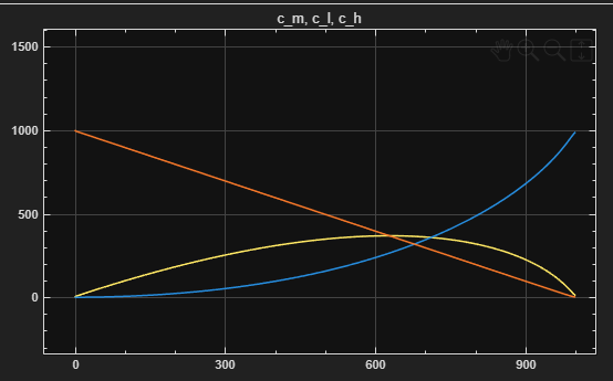
Figure 1 – CH, CM, and CL vs. Time
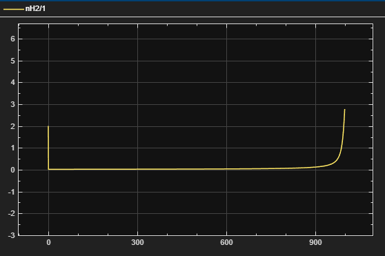
Figure 2 – nH2 vs. Time
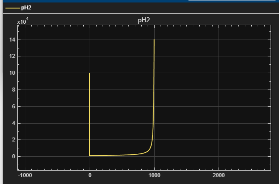
Figure 3 – pH2 vs. Time
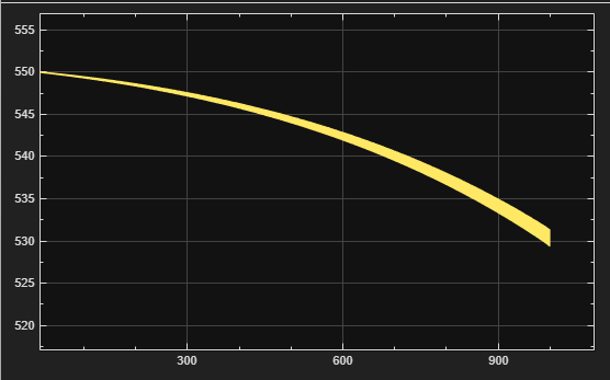
Figure 4 – Tcool vs. Time
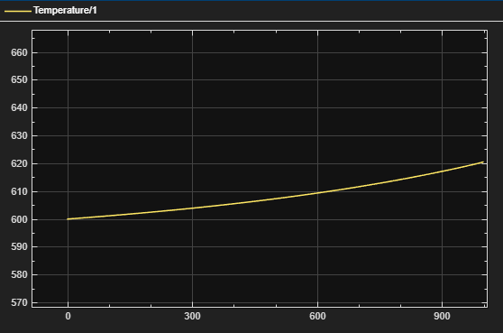
Figure 5 – Temp vs. Time
-
Heavy paraffins (CH):
dCH/dt = -r1 -
Isoparaffins / intermediates (CM):
dCM/dt = r1 - r2 -
Light alkyl products (CL):
dCL/dt = r2
-
Lumped hydrocracking rates:
r1 = k1(T) · CH · H^α
r2 = k2(T) · CM · H^α -
Arrhenius temperature dependence:
k_i(T) = k0_i · exp( -Ea_i / (R·T) ), i = 1, 2 -
CH = heavy paraffins [mol/m³]
-
CM = isoparaffins / intermediates [mol/m³]
-
CL = light products [mol/m³]
-
H = PH2 / (R·T) = hydrogen concentration
-
k0_i = pre-exponential factor
-
Ea_i = activation energy
-
α = hydrogen order of reaction
dnH2/dt = FH2_in – νH·(r1 + r2)·Vliq – Fvent
- nH2 = moles of hydrogen
- FH2_in = inlet hydrogen feed (PID output)
- νH = hydrogen consumed per reaction
- Vliq = liquid reactor volume
- Fvent = kvent·(PH2 – Pset) (if PH2 > Pset)
PH2 = (nH2 · R · T) / Vgas
- PH2 = hydrogen partial pressure
- Vgas = gas headspace volume
- R = gas constant
- T = reactor temperature
dT/dt = [ –ΔHrxn·(r1 + r2) – (UA/Vliq)·(T – Tcool) ] / (ρ·Cp)
- ΔHrxn = heat of reaction (negative, exothermic)
- ρ·Cp = effective thermal capacitance
- U·A = heat transfer coefficient × area
- Tcool = coolant temperature (PID output)
Error:
eP = Pset-PH2
Control law:
Fvent = Kp_P·eP + Ki_P∫eP dt + Kd_P·d(eP)/dt
Error:
eT = T-Tset
Control law:
ΔTcool = Kp_T·eT + Ki_T∫eT dt + Kd_T·d(eT)/dt
Coolant temperature:
Tcool = clamp(550 + ΔTcool, Tmin, Tmax)