TGR is a Raspberry Pi (4B) based 4wd robot created for real-world ML/RL-based projects. The robot can perform the line-following task using the camera image only, and the robot can be controlled using an Android App. I plan to implement projects involving ML and RL using the robot.TGR form factor was updated on Jan 2022 to make it smaller, to include fisheye camera lens and to include new sets of lights.

Here's TGR following a Yellow line:

The original video can be found here.
Here are the steps for the line following task:


The auto_runner.cpp file contains the code for the line following task, which is run in the Raspberry PI. The code uses the following 2 header files: img_process.h, threadsafe_stack.h. The image capture is set to 40 FPS, which takes about 25ms per image. Image processing takes about .75ms.
The following command is used in the terminal for compiling auto_runner.cpp:
g++ -std=c++17 auto_runner.cpp `pkg-config opencv4 --cflags --libs` -pthread -lwiringPi -o auto
The command for running auto_runner:
./auto
TGR has tank-like controlling: To move left, the right motors are given power, and to move right, the left motors are given power. Here's TGR running around:

The robot is controlled using an Android app. The top part of the following GIF contains the screen recording of the Android app while controlling the robot. The bottom part is a real-time video of the robot.

High res videos can be found here and here (Change the quality to 1080p). For this demonstration, the previous form factor of TGR was used.
In this section, details about the components/materials/tools and the connections will be provided.
Note: URL with an asterisk means that the URL is of a local Bangladeshi website, who does not ship to other countries.
Electrical components
| Sl | Name | Number | URL |
|---|---|---|---|
| 1 | Raspberry PI 4B, 4gb | 1 | URL |
| 2 | Raspberry Pi Camera Module V2 | 1 | URL |
| 3 | Battery (Power Bank, 20000mAh) | 1 | URL |
| 4 | Motor Driver (TB6612FNG) | 2 | URL |
| 5 | PWM Controller (PCA9685) | 1 | URL |
| 6 | 12v 400 RPM Geared Motor | 4 | *URL |
| 7 | 12v DC Fan | 1 | *URL |
| 8 | 12v Led Light | 2 | URL |
| 9 | QC2.0/3.0 Decoy Trigger Board | 1 | URL |
| 10 | USB 2.0 Jack Connector A type | 2 | URL |
| 11 | Jumper Wires | - | URL |
| 12 | Type-c Cable | 1 | URL |
Build Materials
| Sl | Name | Number |
|---|---|---|
| 1 | Depron foam board (2ft by 2ft, 5mm, Gray) | 1 |
| 2 | Screws (5-20mm M2 and 6-10mm M3) | - |
| 3 | Super Glue | 1 |
| 4 | *Wheels (85x38mm) and *Hexa connector (4mm) | 4 |
| 5 | Transparent acrylic sheet (1ft by 1ft, 3mm) | 1 |
Tools
| Sl | Name |
|---|---|
| 1 | Anti cutter |
| 2 | Steel scale |
| 3 | Electric screw driver (Tolsen) |
| 4 | Soldering iron and solder wire |
| 5 | Wire cutter |
Comments on Hardware
It might not be obvious why I am using this particular power bank or the fan. The power bank has multiple outputs and is powerful enough to run the PI and the components. Also, it supports both 5v and 12v output. 5v is needed to power the PI, the motor drivers and the PWM controller. The 12v output can be achieved using the USB QC2.0/3.0 decoy trigger. The motors, the lights and the fan require 12v power. The 12v fan serves two purposes. It cools the PI CPU and also draws power from the USB port so that the power bank does not turn off the USB port. Without it, the power bank will turn the USB port off and the motors/lights will not get any power.
The following diagrams show the connections between the PI, the motor drivers, the PWM controller, the power bank, the motors and the lights. 12v power comes from the USB QC2.0/3.0 decoy trigger output. The Wiring PI pinouts are different than the Broadcom GPIO pinouts. Here's a high res image of the WiringPI pinout.
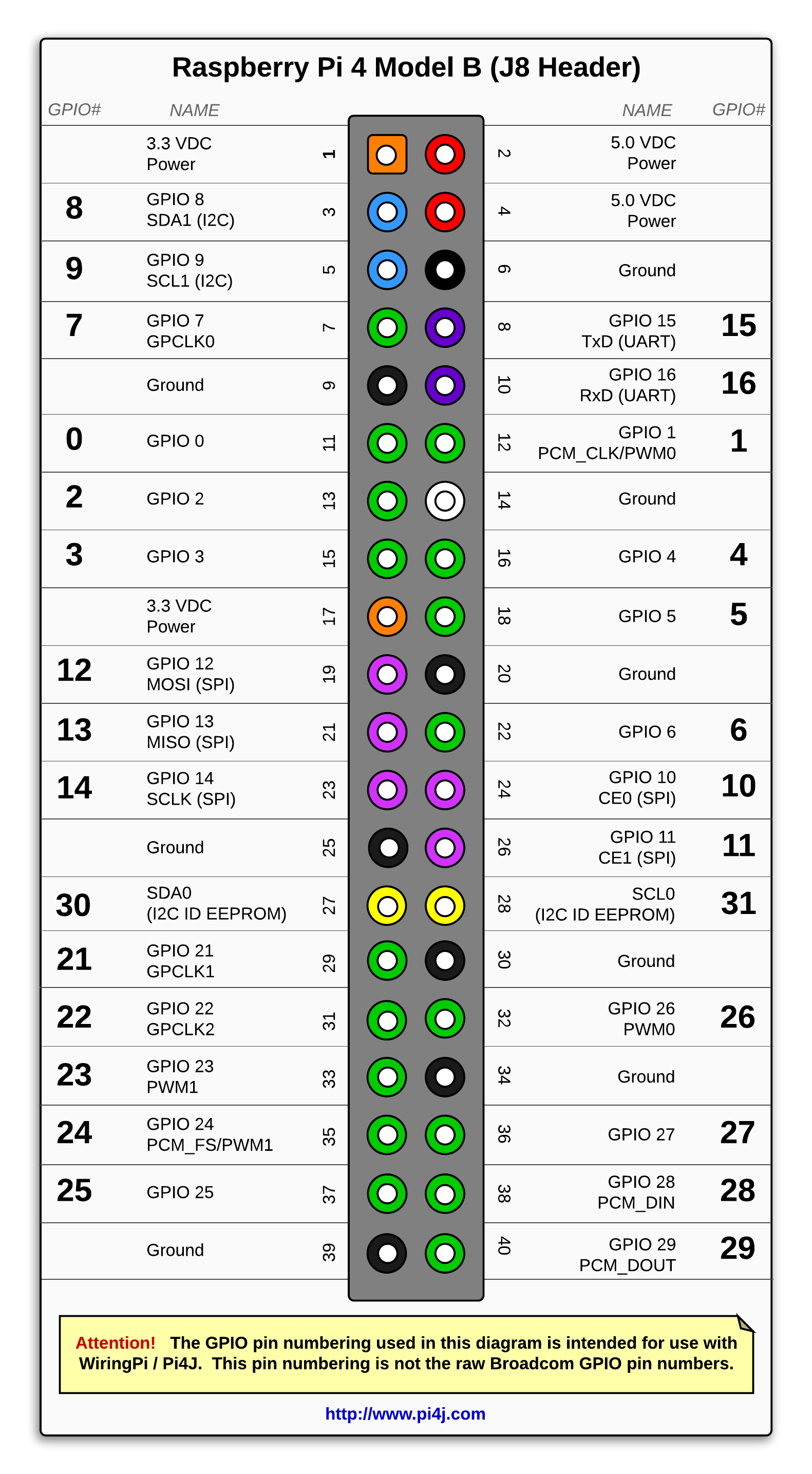


(Click the images for better resolution)
The PI mainly runs a C++ program which is used for:
- Receiving commands from the Android App for driving the motors
- Receiving commands for turning the lights on or off
- Sending the video data generated by the PI camera to the Android App
The mobile_runner.cpp contains the code for these tasks. The C++ code uses the following libraries:
- OpenCV for Raspberry PI (I followed this article to install OpenCV, turned off GStreamer)
- WiringPI (Installation URL)
- PWM Controller (pca9685) Driver (Installation URL)
Note: The WiringPI is deprecated. But, I will not update my project yet because the PWM Controller Driver still uses WiringPI.
The following command is used in the terminal for compiling mobile_runner.cpp:
g++ mobile_runner.cpp -o mobile_runner `pkg-config opencv4 --cflags --libs` -pthread -lwiringPi
The command for running mobile_runner:
./mobile_runner
The Android App is used for motor, light control and to see the video stream from the robot. The TGR_Android contains the Android App codes.
The app contains two JoystickViews, one for controlling the left motors, other for the right motors. Changing the position of a JoystickView upwards will turn the corresponding motors in the forward direction, and changing the position downwards will turn the motors in the backward direction. The JoystickViews also control the motors' speed. Full upward position of the JoystickView will result in full forward power, half upward position will result in half forward power. It also contains a button, which can be used for turning the lights on/off. In the middle of the app, the PI camera's video stream can be seen. The video stream can be used to control the robot in real-time.

The Android App is connected with the mobile_runner program through sockets for sending and receiving data. To make that happen, the two devices are connected to the same wifi network. The Android App acts as server; the mobile_runner.cpp contains the ip address (line 23) of the Android device for connection. The ip address of the Android device was fixed in the wifi router settings.
- PI camera has only around 62.2 x 48.8 degrees FoV. I am considering a camera with a higher FoV.
- The robot's movement mechanisms are set in such a way so that it can be easily used in RL projects. I am currently working on implementing RL algorithms on the robot for performing simple tasks.
- The overall connection system between the Android device and the Raspberry PI can be further improved.